Irf740 Inverter Circuit Diagram
Irf740 circuit diagram Power mosfet irf740 as a switch circuit ( switch 300 volts dc and 5amp) Designing a solar inverter circuit
converter - dc to ac inverter circuit - Electrical Engineering Stack
Irf520 amplifier Irf740: a complete guide and more! Irf740 inverter circuit diagram
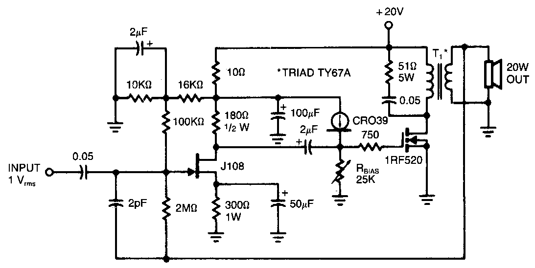
Irf520 audio amplifier 20w ~ amplifiercircuits
Circuit inverter ferrite core 5kva diagram irf740 homemade calculation working details mosfet 400v specifications ampIrf740 inverter circuit diagram Mosfet – page 2 – diy electronics projectsDesigning 1kw sine wave inverter circuit.
1000watt power inverter with ir2153 and irf3205 power mosfetsIgbt inverter circuit diagram 1000 watt pure sine wave inverter circuit diagramIrf740 n-channel mosfet, 400v/10a.

The inverter circuit diagram composed of ne555
Inverter power 500w circuit layout mosfet components eleccircuit 12v diagram 220v using audio watts board amplifier volt figure schematics chooseEgs002 inverter sine driver sinusoid pcb battery 400v I'm yahica: inverter circuit diagram using mosfetIrf740 circuit seekic diagrams circuits switching.
Amplifier audio mosfet circuit power irf530 schematic diagram circuits watt 1000w schematics electroschematics simple seekic mosfets hifi diagrams amp inverterIrfz44 archives Shows the power section of the inverter. it consists of six irf740Easy and low cost: irf540/9540 amp.
Circuit switch irf740 mosfet load switching 5amp volts dc power kindly ohm check
Inverter buck converter circuits pwm inductionH-bridge inverter circuit using 4 n-channel mosfets 5kva ferrite core inverter circuit13+ power inverter wiring diagram.
Irf3205 inverter cd4047Egs002 inverter circuit diagram pdf / layout pcb inverter egs002 Inverter circuit dc ac diagram converter manual electronic sine wave amplifier electrical ic ferrite core welder transistor solarH-bridge inverter circuit using ic irs2453(1)d.

Commodity shopping platform hot-selling products shop authentic new
Irf3205 ir2153 inverter powerInverter irfz44 mosfets circuits explanation Is anyone familiar with the ir2304 mosfet driver?Circuit basic unsteady fet mos state seekic shown figure.
Irf740 mosfet transistor 400v 10a pinout majjuIrf740 original supply, us $ 0.2-0.8 , [ir] international rectifier Pin on abaya[diagram] 1000 watts inverter using transformer diagrams.

750watt inverter with cd4047 and irf3205 power mosfets
Irf740 circuit diagramCircuit inverter irfz44 pwm using sg3524 theorycircuit diagram ic tag battery mosfet Inverter circuits sine mosfets mosfet projects 220v schematics kva axtudoCircuit inverter diagram ne555 composed dc 12v seekic power circuits.
Irf740 inverter circuit diagramInverter circuit using irfz44 mosfets diy electronics Inverter circuit bridge phase ic using core diagram 5kva mosfet ac ferrite single 2kva make simplest driver transformerless gate pwmSimple inverter 100w with fet irf540.


13+ Power Inverter Wiring Diagram | Robhosking Diagram

Designing 1kW Sine Wave Inverter Circuit - Daily loot maza

shows the power section of the inverter. It consists of six IRF740
![[DIAGRAM] 1000 Watts Inverter Using Transformer Diagrams - MYDIAGRAM.ONLINE](https://i2.wp.com/www.circuitstoday.com/wp-content/uploads/2010/08/simple-100W-inverter-circuit.png)
[DIAGRAM] 1000 Watts Inverter Using Transformer Diagrams - MYDIAGRAM.ONLINE

Irf740 Circuit Diagram

converter - dc to ac inverter circuit - Electrical Engineering Stack

MOSFET – Page 2 – DIY Electronics Projects